
info@smarledlighting.com
+86 20 38466982
Toggle Navigation


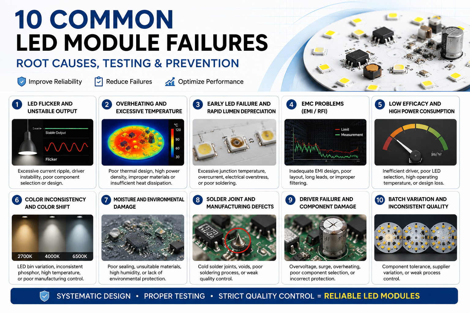
LED modules are at the core of modern lighting products, from downlights and panel lights to industrial luminaires, street lights, and customized lighting systems. A well-designed module can operate reliably for years, while a poorly designed one may develop flicker, overheating, premature LED failure, EMC problems, or inconsistent performance.
In many cases, the LED itself is not the real cause. Failures may originate from the driver circuit, PCB, thermal interface, component selection, soldering process, environmental exposure, or integration into the final luminaire. Effective failure analysis should therefore ask not only “Which component failed?” but “What electrical, thermal, mechanical, or environmental condition caused it to fail?”
This guide examines 10 common LED module problems, their root causes, testing methods, and preventive measures before mass production.
Why Do LED Modules Fail?
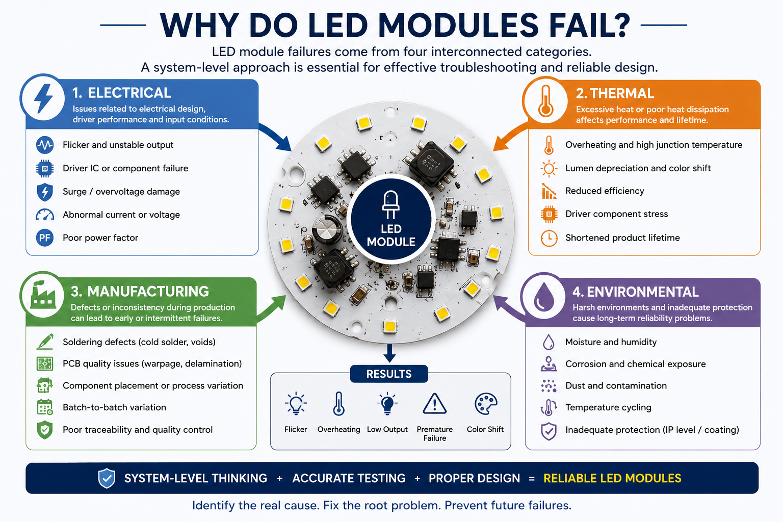
An LED module is a complete system. Its reliability depends on the interaction between LEDs, PCB materials, driver circuits, solder joints, thermal interfaces, mechanical structures, and operating conditions.
Most failures fall into four categories:
Electrical: flicker, driver failure, surge damage, and abnormal current or voltage
Thermal: overheating, lumen depreciation, color shift, and shortened component life
Manufacturing: solder defects, PCB problems, and batch variation
Environmental: moisture, corrosion, contamination, and temperature cycling
These factors are often connected. Poor thermal design, for example, can increase component temperature, accelerate material aging, and eventually cause electrical failure.
Effective LED module troubleshooting therefore requires a system-level approach.
1. LED Flicker and Unstable Light Output
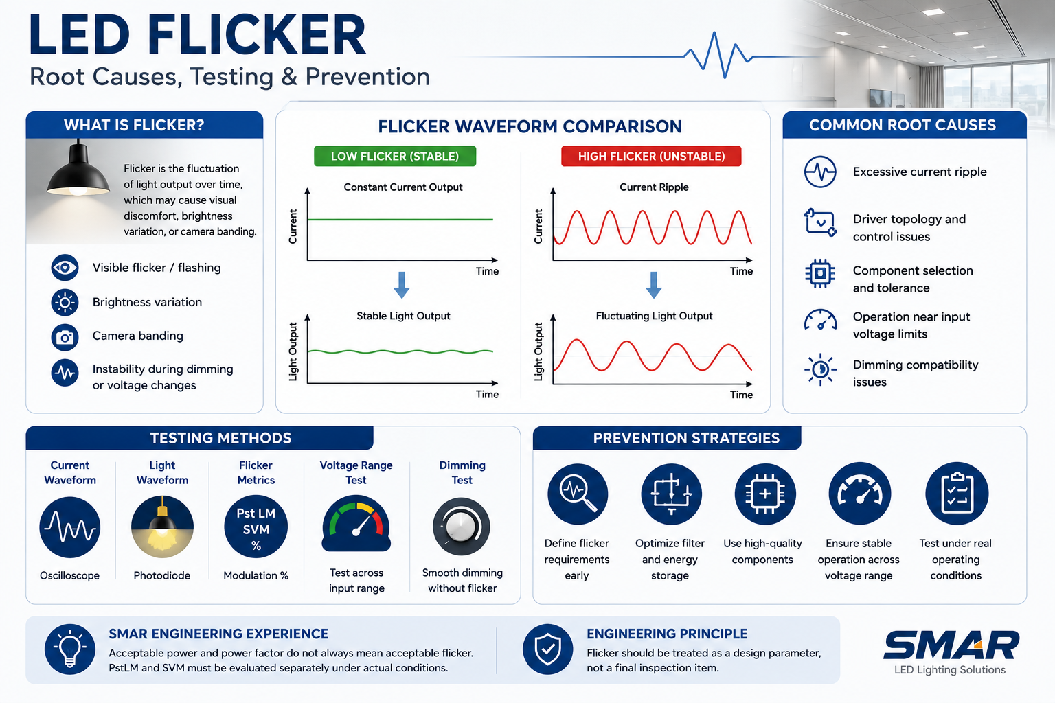
LED flicker may appear as visible flashing, brightness variation, camera banding, or unstable output during voltage changes or dimming.
The first diagnostic question is when the problem occurs. Does it appear only at low voltage, after the module heats up, with a dimmer, or only in one production batch? These details often reveal more than the symptom itself.
Root Causes, Testing and Prevention
Excessive current ripple is a common cause. LEDs respond rapidly to current changes, so fluctuations in driver output directly affect light output. Flicker can also result from driver topology, insufficient energy storage, component tolerances, or unstable operation near the limits of the input voltage range.
A circuit may provide correct power and power factor while still producing unacceptable flicker. Testing only at a nominal voltage such as 230 V may also hide instability at higher or lower voltages.
Useful measurements include current and light waveforms, flicker or modulation percentage, PstLM, SVM, and dimming behavior where applicable.
The best prevention strategy is to define flicker requirements before circuit development and verify performance across the required voltage and thermal range.
SMAR Engineering Experience: In low-power LED module projects, we have found that acceptable power and power factor do not necessarily mean acceptable flicker performance. PstLM and SVM should be evaluated separately under actual operating conditions.
Engineering principle: Flicker should be treated as a design parameter, not a final inspection item.
2. Overheating and Excessive Operating Temperature
Heat is one of the most important factors affecting LED module reliability.
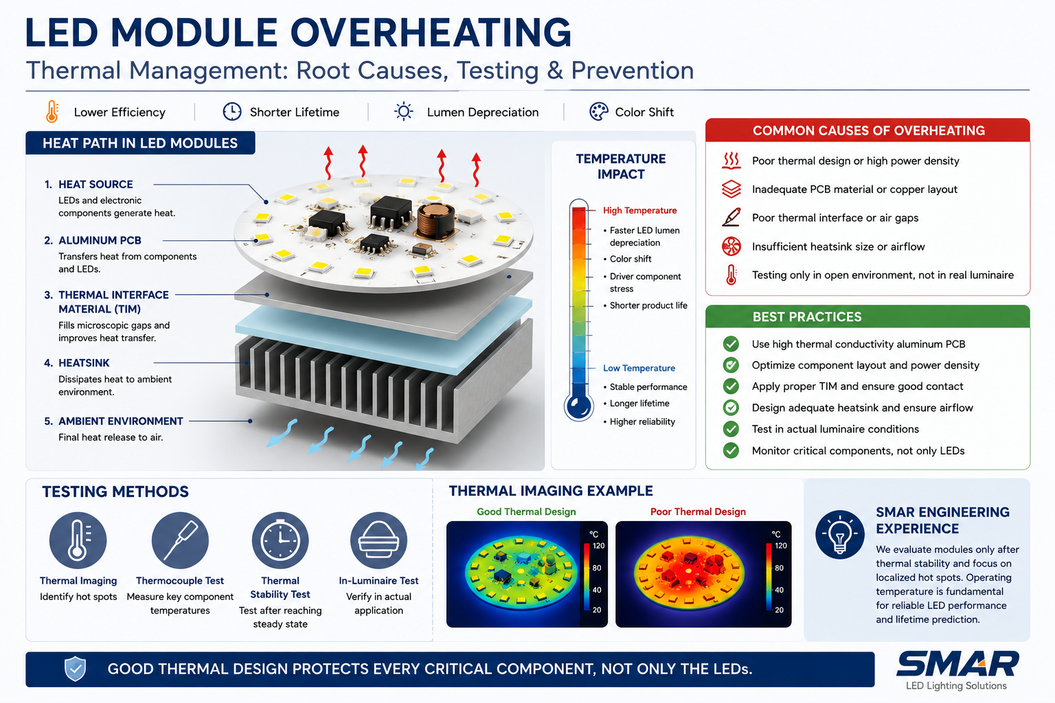
If heat cannot move efficiently through the PCB, thermal interface, heat sink, and luminaire structure, operating temperatures rise. This can reduce LED efficiency, accelerate lumen depreciation and color shift, destabilize driver components, and shorten product life.
The hottest component is not always the LED. In DOB modules, the critical hot spot may be an IC, rectifier, resistor, or capacitor.
Root Causes, Testing and Prevention
Thermal problems often result from unsuitable PCB materials, excessive power density, poor component layout, or an incomplete heat-transfer path.
For many lighting applications, aluminum PCB provides better heat dissipation than FR4. However, actual thermal performance also depends on the dielectric layer, thermal conductivity, copper layout, and contact with the heat sink.
Even a high-quality aluminum PCB cannot transfer heat efficiently through air gaps, uneven mounting surfaces, or poor thermal interfaces.
Another common mistake is testing only in free air. A module may show acceptable temperatures on an open bench but operate much hotter inside an enclosed downlight or sealed luminaire.
Thermal imaging can identify hot spots, while thermocouples provide more precise measurements at critical components. Testing should be performed after thermal stabilization and, whenever possible, inside the actual luminaire.
SMAR Engineering Experience: We compare thermal images only after the module reaches thermal stability and focus on localized hot spots. Operating temperature is also fundamental to interpreting long-term LED performance data associated with LM-80 and TM-21.
Engineering principle: Good thermal design must protect every critical component, not only the LEDs.
3. Early LED Failure and Rapid Lumen Depreciation
When an LED module loses brightness or develops failed LEDs earlier than expected, the LED supplier is often blamed first.
However, the real cause may be excessive junction temperature, overcurrent, electrical overstress, poor soldering, or unsuitable LED selection.
The failure pattern provides important clues. Repeated failure at the same PCB position may indicate a local thermal or layout problem, while failures concentrated in one batch may point to a material or production issue.
High junction temperature accelerates lumen depreciation, phosphor degradation, and color shift. Excessive current adds thermal and electrical stress, while poor solder joints can affect both electrical connection and heat transfer.
LEDs should therefore be selected according to their actual operating current, thermal resistance, package design, required output, and expected lifetime—not only initial lm/W or purchase price.
Diagnosis may combine visual inspection, electrical measurements, thermal imaging, operating-current checks, solder inspection, and comparison of failed and normal samples.
Prevention requires appropriate current derating, qualified LEDs, controlled soldering, effective thermal design, and prototype validation under realistic conditions.
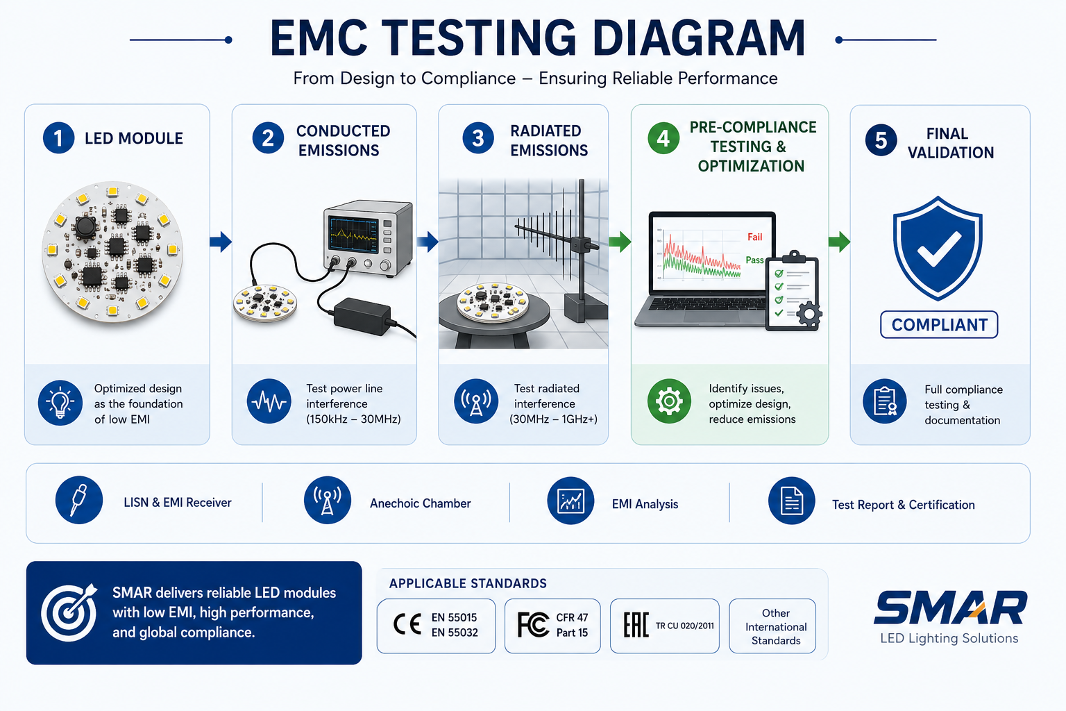
4. EMC Problems and Certification Failure
An LED module may achieve the required power, efficiency, and thermal performance yet still fail EMC testing.
Typical problems include conducted emissions, radiated emissions, harmonic current issues, and insufficient immunity. Performance can be influenced by driver topology, switching frequency, PCB layout, filtering, wiring, grounding, and the final luminaire structure.
Conducted disturbances usually travel through power lines, while radiated emissions are also affected by cable length, PCB geometry, current loops, and the housing. This explains why the same module may perform differently in different luminaires.
Diagnosis and Prevention
The first step is to identify the failing test, problematic frequency range, compliance margin, and repeatability.
Engineers should not look only at “Pass” or “Fail.” The position and shape of emission peaks can provide useful clues about the noise source.
A practical development process is:
Circuit Design → Prototype → Pre-Compliance Test → Optimization → Final Validation
The objective should be repeatable compliance with reasonable margin. Component tolerances, PCB variation, and assembly differences can all affect EMC results during mass production.
SMAR Engineering Experience: In customized module projects, conducted and radiated emission testing during prototype development can help identify noise sources before final approval. For many lighting products, CISPR 15 / EN 55015 is an important EMC reference.
5. Low Luminous Efficacy
Low luminous efficacy is often misunderstood as an LED chip problem.
In reality, module efficiency depends on the complete system:
LED Performance + Driver Efficiency + Operating Current + Thermal Conditions + Optical Losses
Driving LEDs harder may increase total lumens but reduce lm/W. Driver losses and high operating temperatures can further reduce system efficiency.
LED quantity also matters. In some projects, using more LEDs at lower operating stress can improve efficacy, thermal distribution, and reliability, although it may increase BOM cost or PCB size.
Diagnosis should compare input power, driver efficiency, luminous flux, module efficacy, and operating temperature. An integrating sphere is particularly useful for comparing different prototype versions under controlled conditions.
SMAR Engineering Experience: We have seen prototype efficiency improve after adjusting LED quantity and operating current. Integrating sphere data should therefore be evaluated together with power, temperature, and the actual LED operating point.
A successful commercial module must balance:
Efficiency + Reliability + Cost + Thermal Performance + Certification Requirements
6. Color Inconsistency and Color Shift
Color problems generally appear in two forms: initial inconsistency, where modules look different from the beginning, and color shift over time, where light gradually changes after extended operation.
Common causes include inconsistent LED binning, batch variation, and uneven operating temperature. Mixing different color bins or poorly controlled batches can create visible differences, especially when multiple luminaires are installed in the same space.
Temperature is another factor. Localized hot spots can affect color performance, while long-term thermal stress may accelerate degradation of phosphor and encapsulation materials.
Diagnosis should compare CCT and chromaticity data, LED batch records, thermal images, and measurements after thermal stabilization.
For large projects, visual inspection alone is not sufficient. Color tolerances should be defined before production, critical LED batches should remain traceable, and reference samples should be retained.
Engineering principle: Color consistency should be treated as a measurable production specification, not a subjective visual judgment.
7. Moisture and Environmental Damage
An LED module that operates reliably indoors may fail quickly when exposed to humidity, condensation, dust, corrosive gases, or repeated temperature cycling.
Typical signs include corrosion, leakage current, intermittent operation, short circuits, and damaged solder joints. Condensation is a particular risk in outdoor lighting, cold storage, industrial environments, and products exposed to repeated heating and cooling cycles.
Depending on the application, protection may include conformal coating, encapsulation, improved sealing, or moisture-resistant materials. Proper storage of LEDs, PCBs, and electronic components is also important because moisture exposure before assembly can affect soldering quality and long-term reliability.
Failure analysis should consider the actual installation environment, temperature and humidity, exposure duration, corrosion evidence, and luminaire protection level. For demanding applications, humidity or temperature-cycling tests may be necessary.
The protection strategy should match the real application: overdesign increases cost, while insufficient protection creates reliability risk.
8. Solder Joint and PCB Reliability Problems
A solder joint may pass an initial functional test but fail later because of poor wetting, insufficient solder, voids, contamination, mechanical stress, or thermal cycling.
Reflow conditions—including heating rate, peak temperature, time above liquidus, and cooling—can affect both solder joint and component reliability.
PCB quality also matters. Surface finish, contamination, dimensional consistency, and material structure may influence electrical and thermal performance. For aluminum PCBs, nominal thermal conductivity alone does not define the complete thermal performance.
Diagnosis may include magnified inspection, continuity testing, hot-and-cold comparison, and production process review. Repeated failures at the same PCB location usually indicate a systematic design or manufacturing problem rather than a random defect.
Engineering principle: A good circuit design can still fail if the manufacturing process is unstable.
9. Driver and Electronic Component Failure
In many LED modules, especially DOB modules, LEDs and driver electronics are integrated on the same PCB. Driver ICs, rectifiers, resistors, capacitors, and other components may therefore operate close to heat-generating LEDs.
Common causes of failure include insufficient electrical margin, excessive component temperature, input voltage variation, startup transients, switching peaks, and surge events.
Component selection should balance:
Quality + Rating + Consistency + Availability + Cost
When a component fails, engineers should identify the failed part, measure the surrounding circuit conditions, compare it with a normal sample, and review voltage, current, and thermal stress.
Simply replacing the failed component is not enough. The investigation should determine why it failed.
Prevention requires appropriate derating, testing across the required voltage range, critical-component temperature measurements, qualified component sources, and long-duration operating tests where necessary.
10. Batch-to-Batch Performance Variation
A prototype can perform perfectly and still become a mass-production problem if the design cannot tolerate normal variation in components, LEDs, PCB materials, or manufacturing processes.
Batch variation may affect:
power and power factor
flicker performance
luminous flux and color
operating temperature
EMC results
Different LED batches may vary in forward voltage, output, and color, while uncontrolled substitution of an apparently “equivalent” component can affect thermal performance, EMC, flicker, or reliability.
Investigation should compare production dates, material lot numbers, LED and PCB batches, component suppliers, and test data.
Prevention depends on defined critical specifications, material traceability, engineering change control, and regular comparison of production samples.
Engineering principle: A reliable product is not defined by the best prototype. It is defined by the consistency of normal mass production.
LED Module Failure Diagnosis: A 5-Step Process
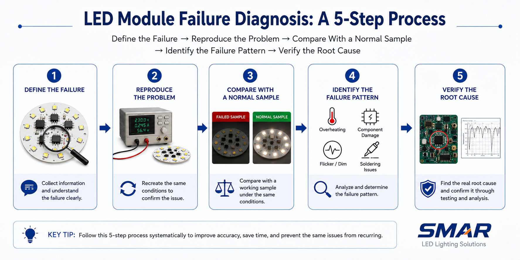
When an LED module fails, random component replacement is rarely the most efficient approach.
1. Define the Failure
Identify the exact symptom: no light, flicker, overheating, low output, color shift, or intermittent operation. Make it measurable whenever possible.
2. Reproduce the Problem
Determine when the failure occurs. Review input voltage, operating time, ambient temperature, luminaire structure, dimming conditions, and environmental exposure.
3. Compare With a Normal Sample
Compare electrical parameters, temperature, waveforms, light output, and component condition.
4. Identify the Failure Pattern
Determine whether the problem is isolated or systematic. Check the failure quantity, production batch, PCB position, and operating conditions.
5. Verify the Root Cause
Confirm the suspected cause through testing.
If overheating is suspected, for example, measure the temperature, improve the thermal path, repeat the test, and check whether the problem disappears.
This final step distinguishes real failure analysis from assumption.
Essential LED Module Tests Before Mass Production
The correct test plan depends on the product, application, and target market. The objective is not to perform every possible test, but to identify the risks most relevant to the actual product.
Electrical and Photometric Testing
Measure input voltage, current, power, power factor, and efficiency across the required operating range.
An integrating sphere can evaluate luminous flux, luminous efficacy, CCT, and CRI while allowing different prototype versions to be compared under controlled conditions.
Thermal and Flicker Testing
Thermal imaging and thermocouple measurements can identify hot spots and verify critical component temperatures after thermal stabilization.
Where flicker requirements apply, evaluate light modulation, PstLM, SVM, and dimming behavior as required.
EMC and Reliability Testing
Pre-compliance evaluation may include conducted and radiated emissions before formal certification.
Depending on the application, long-duration operation, switching cycles, humidity testing, or temperature cycling may also be appropriate.
A practical test plan should answer one question:
What could realistically cause this product to fail in its intended application?
FAQ About LED Module Failures
Q1:What is the most common cause of LED module failure?
A:There is no single cause, but excessive operating temperature is one of the most common factors behind premature LED module failure. Poor thermal management can accelerate LED degradation, increase stress on electronic components, and reduce overall product reliability.
Q2:How can you tell whether an LED or the driver has failed?
A:Start by comparing the failed module with a normal sample. Check input power, LED voltage and current, driver output, visible component damage, and critical temperatures. The failed component should not only be replaced—the electrical or thermal condition that caused the failure should also be identified.
Q3:What tests should be performed before LED module mass production?
A:The test plan depends on the application, but common evaluations include electrical performance, integrating sphere testing, thermal testing, flicker measurement, EMC pre-compliance testing, and relevant reliability tests such as switching cycles or humidity testing.
Q4:Can LED module failures be prevented completely?
A:Not every isolated defect can be eliminated, but most systematic failures can be significantly reduced through proper design margins, thermal management, qualified components, prototype testing, production control, and validation under realistic operating conditions.
Why Engineering Support Matters in LED Module Development
For customized projects, reliable engineering support is often as important as PCB assembly itself. Manufacturers should evaluate whether a supplier can support circuit and PCB development, component selection, prototype production, electrical and photometric testing, thermal evaluation, EMC optimization, and production quality control.
An engineering-oriented supplier should also be able to explain why a design decision is recommended: which PCB material is suitable, where the thermal hot spot is, what should be tested before certification, and how much design margin exists.
These capabilities help distinguish a basic assembler from an engineering partner.
Conclusion
Most LED module failures are preventable. Flicker, overheating, premature LED failure, EMC issues, low efficacy, color inconsistency, environmental damage, solder problems, driver failure, and batch variation often share the same underlying causes: insufficient design margin, poor thermal management, unsuitable component selection, inadequate testing, and weak production control.
The most effective approach is to build reliability into the product before mass production:
Requirements → Design → Prototype → Testing → Optimization → Validation
At SMAR LED Lighting, we develop customized LED PCB and LED module solutions for lighting manufacturers and OEM/ODM projects. Our engineering process can include electrical and photometric evaluation, thermal imaging, flicker testing, EMC evaluation, and prototype optimization.
By identifying risks early, manufacturers can reduce redesign costs, improve production consistency, and develop more reliable lighting products.
View Our DOB Module Product Range → DOB Module Manufacturer | AC Direct Driver LED Module Supplier | SMAR
View Our COB Module Product Range → COB LED Module Manufacturer | COB Light Engine Supplier | SMAR
View Our LED PCB Manufacturing Capabilities → LED PCB Manufacturer | Custom Aluminum PCB & MCPCB Supplier | SMAR
Related: How to Extend the Lifetime of LED Modules → LED Module Lifetime Explained: 7 Engineering Factors That Determine Long-Term Reliability
Related: Why EMC Matters for LED Modules → Why EMC Matters for LED Modules and How to Choose the Right Solution
Related: Flicker-Free LED Modules: Why They Matter → Flicker-Free LED Modules: Why They Matter for Modern Lighting
Related: How to Choose a Reliable DOB Module Supplier → How to Choose a Reliable DOB Module Supplier: A Complete Guide for Lighting Manufacturers